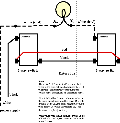
My brother has usually done this for me, however, recently, he has been occupied with his own building project and I have, in addition to a couple of remaining 3-way circuits in my own project, been sort of supervising the wiring of a friend's new home. Consequently, I have had to learn to fly with my own wings. I used to have to look this up every time, but I've got my own favorite solution here.
It is possible to power the circuit by home-running the principal lighting fixture box instead of one of the switch boxes. I personally reject the concept of powering anything except switch boxes for I don't like to find power up in my lights when the switch is off. Doing it that way also prohibits using a dimmer.
Here is how I do it.
I run 14-3 with ground from one switch box through one lighting fixture box and then to the other switch box. I choose one of the switch boxes to run power to and I put a piece of black tape around the 14-3 cable in the other (unpowered) box. Later, after stripping the insulation off the cable to prepare this (unpowered) switch box for inspection, I take the piece of tape and wrap it around the white wire from the cable. This is to show that it is acting as the hot wire in the portion of the circuit between the lighting fixtures and this (unpowered) switch box. It is connected to the common lug of that (unpowered) switch.
The black and red wires in the 14-3 with ground cable flip between powering and not powering the lights. Their color is not really significant, however, hooking the same color to a different pin on each switch, as shown below, creates the case in which the light is off when both switches are in the same state, and on when the switches are in opposite states to each other. This is not the only way the switches can work for it can be set up so that the light is on when both switches are in the same state and off when they are opposite. This is done by cross-connecting the colors in place of how I said to do it here. It doesn't really matter, as an obsessive-compulsive, I prefer it the way I have shown it here.
Of course, as shown, the red and black wires of the 14/3 with ground cable are run straight through the lighting fixture box. It would not matter except for the elegant symmetry of the solution, sometimes very important when you're as befuddled as I am.
So, speaking of symmetry, the only thing asymetrical or bizarre about this solution is that in the lighting fixture box, it is the white lead of the 14/3 cable that acts as both hot and neutral (marked "cold" here in the diagram).
Of course, the grounds are all prepared as normal using green nuts in the switch boxes to unite the two ground wires and tie to the (green) grounding screw on the switch. In the lighting fixture box, depending on the type of fixture (can, fan, chandelier, etc.), a green nut may be used to tie the grounds together with the fixture ground.
In the diagram below, the lighting fixture box is illustrated by the faint dotted line while the switches themselves are not shown in boxes, including the switch where the permanent electrical supply is run. The symmetry to see here is at the "common" lug on the 3-way switch: it always contacts the hot wire—black in the switch box that is home run to the load center and the black-taped white wire from the 14-3 cable that is acting as hot (as marked by the aforementioned tape).
