Fixed mounting of solar panels is a consideration as reorienting them even only a couple of times a year can get tedious, dangerous or impossible. Tedious because few are the humans who relish periodic maintenance tasks, dangerous in that panels are often located on rooftops, and impossible when the owner is aged and physical health prohibits him from climbing ladders, teetering on rooftops, etc.
For fixed-angle mounting, please peruse Fixed tilt
This system is under study. It costs money, but is not exorbitant. This research does not constitute an endorsement.
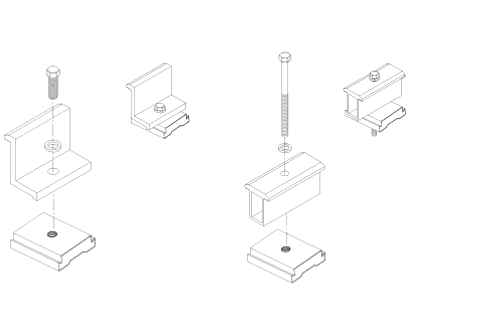
The ProSolar system consists of stand-offs into roof with flashing, rails mounted to stand-offs, and clamps mounted to rails to hold panels. Below is an illustration of clamps. Figure 1 are "end" clamps that grip the edge of one panel while Figure 2 are clamps that grip two edges, i.e.: middle or "in-between" clamps. Below the clamp is a sort of wedge that slides along inside the rail. Tightening its nut head will anchor the clamp in the rail channel.
Approximate prices for ProSolar parts in this system are:
| Rail | 1½" × 136" (11-⅓') | $26 | Shorter, cheaper, but requires 4' on center stand-off mounting |
| Rail | 2½" × 136" (11-⅓') | $34 | 6' on center mounting; choosing this rail—allows for using fewer stand-offs! |
| Stand-offs | 4½" | $8.29 | Bottom rail |
| Stand-offs | 7½" | $12.29 | Taller stand-off to jack top rail up a bit |
| Flashing collar | $6.34 | For each stand-off | |
| End clamps | (various sizes) | $3 | Must determine size needed |
| Middle clamps | (various sizes) | $3 | Must determine size needed |
| Channel nuts | $0.51 | Need one per clamp used |
 Rail, will need 2, mounted at 6 points
on stand-offs |
 Stand-off, 4½,
will need 3; lag-screw into rafter |
 Stand-off, 7½,
will need 3; lag-screw into rafter |
 Flashing for stand-off,
will need 6; tuck under shingle above, overlap shingle below |
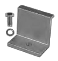 End clamp,
mount panel flat against rail or can be used for multiple purposes |
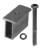 Middle clamp, if
panels to be mounted flat against rail. If 7 panels to be mounted on 12' rail, middle clamps must be used! |
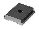 Channel nut, one
per clamp requred. These take up room in the channel! |
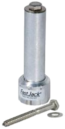
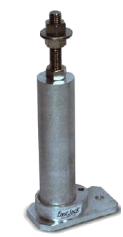
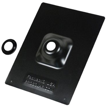
How to install stand-offs with flashing. This is why I bought this system: it's perfect and won't compromise shingled-roof integrity. Click "FastJack™ Installation."
The "material support platform" below is a simple table 24" long with a 14" leg made to sit on a (7/12) roof to offer a horizontal surface on which to set tools and supplies waiting to be used. Could use a sheet of inexpensive ⅝ OSB.
▢ Air ratchet with sockets sized to lag- and other screwheads (and hose)
▢ Ratchet extension
▢ Ratchet
▢ DeWalt drill and bits (one for piloting lag screws, another for piloting sheet metal screws)
▢ Chalk line
▢ Crayon (to mark shingles)
▢ Tape measure
▢ Levels
▢ Material support platform
▢ Stand-offs
▢ Flashing collars
▢ Tar and sealant
▢ Clamps and channel nuts
▢ Rails
▢ Solar panels
▢ Build material support platform (14" leg x 24" table)
▢ Preposition platform, tools and materials to roof
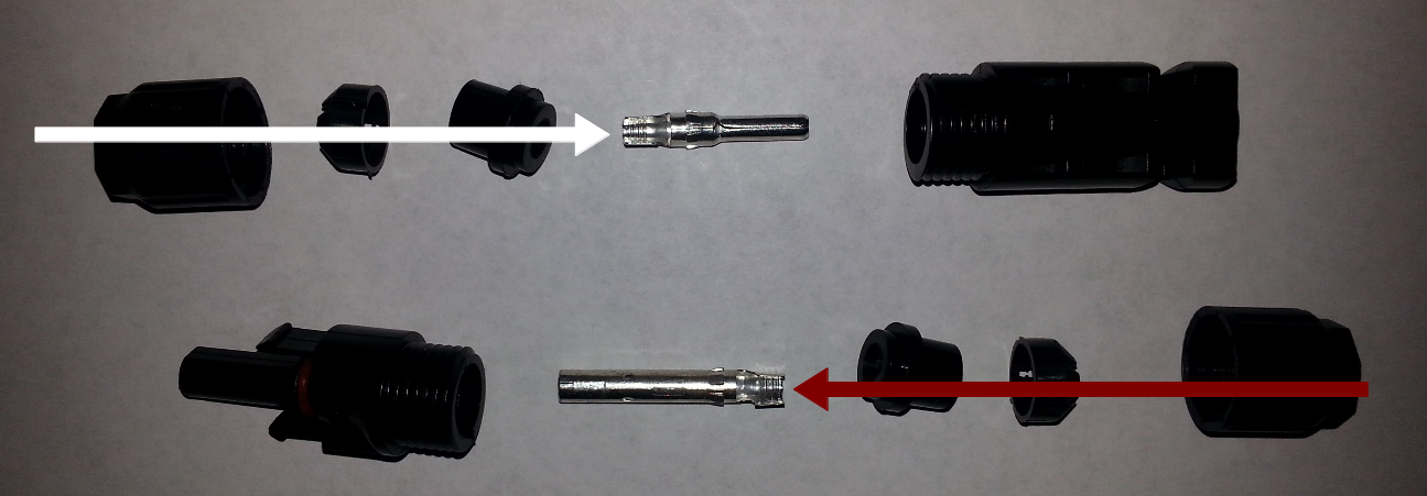
Do clean work with no strands of copper conductor (cable) deflected outside the bayonets. Please note that in both kinds of connector, the tightener goes over the longer segment of the bushing. Here's how to do the male connector:
Assemble the female connector to the conductor (shown in red) using the same technique as shown in the illustration. Once finished, the two conductors can be joined together using the MC4 connector which, once connected, should provide a water-tight, ultraviolet-safe connection.
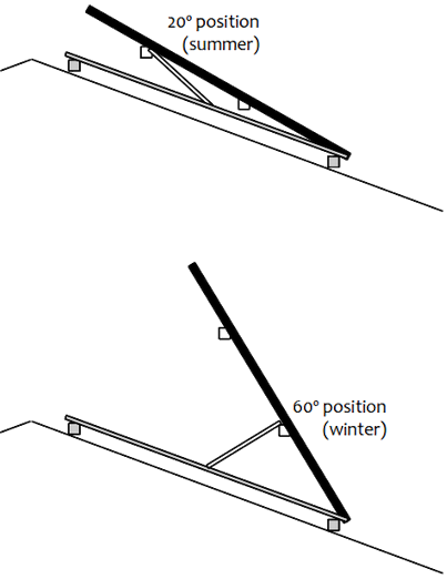
Hell-bent on devising an adjustable system?
Here is, in concept stage only, a simple mounting mechanism to vary solar panels between 20° and 60° (for circa 40° of latitude).
You may find this more trouble than it's worth.