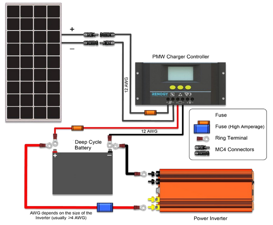
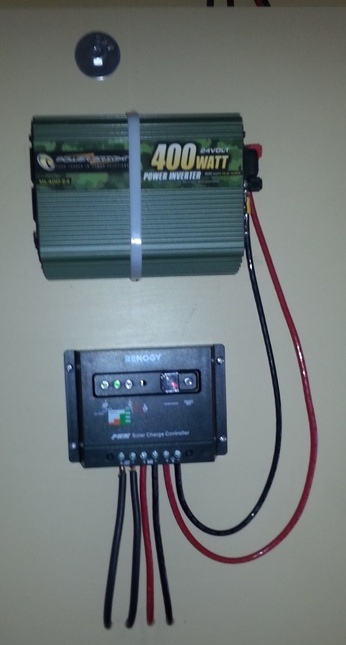
Using the Renogy or another brand charge controller (as shown below), it's fairly easy to wire up your system. In fact, everything is ready and marked for this. All you need to do is ensure the polarities of what you're connecting are correct. This should be very easy for the batteries, since they're well marked and for the inverter, well marked also.
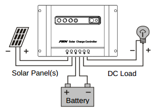
In the diagram above, the inverter is shown connected directly to the battery. The Renogy 30 Ampere controller has terminals for (as shown immediately below, from left to right) the photovoltaic panels, the batteries and the DC load including inverter, instead of connecting the inverter directly to the batteries. Electrically, it's all the same no matter which way you do it. What you must remember, however, is Renogy's strict warning: Do not connect devices such as power inverters, [...] with heavy electrical load that exceed the charge-controller's ratings.
In other words, do not connect some huge inverter whose output exceeds the charge controller's own capacity. This would not be a good idea even if you weren't connecting through the charge controller, but directly to the battery(ies).
What might not be so obvious is the solar panel polarity. It's best not to try to find it. Instead, use this method employing a volt-ohm meter:
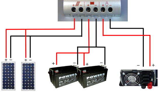
Another wiring diagram, somewhat more pictorial than the one at the top of the page. It uses red for positive and black for negative. Note, however, that the two batteries are in parallel, as would be more common with a 12-Volt system. A 24-Volt system would place the two 12-Volt (or four 6-Volt) batteries in series.
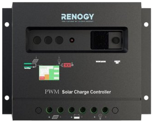
The charge controller is the centerpiece of your solar electric system.
1. Once the battery is connected, the charge controller will illuminate a red light that will turn green when the voltage from the battery is in the right range.
2. Another green light will come on if there is enough sunlight.
3. An orange or red light will indicate that the battery capacity is low and the batteries need recharging. Do not connect devices to the DC load/inverter until there is enough charge as indicated.
4. An LED light is associated with each subsystem. The lights are shown in the image below (green, green and orange) left of center of the charge controller. From left to right, the lights mean:
| System | Description | ||||||||||
|---|---|---|---|---|---|---|---|---|---|---|---|
| Solar panels |
|
||||||||||
| Battery |
|
||||||||||
| DC load/inverter |
|
* Disconnect part or all of the load, that is, unplug one or all devices drawing power from the inverter. This would be a fairly common error meaning (in order of likelihood):
** Disconnect immediately the inverter and/or all devices connected to it. Diagnose this problem. This will require some electrical understanding. If you've correctly connected your inverter and you're not abusing any devices by messing with them electrically, this would be an extremely uncommon error and should never happen.
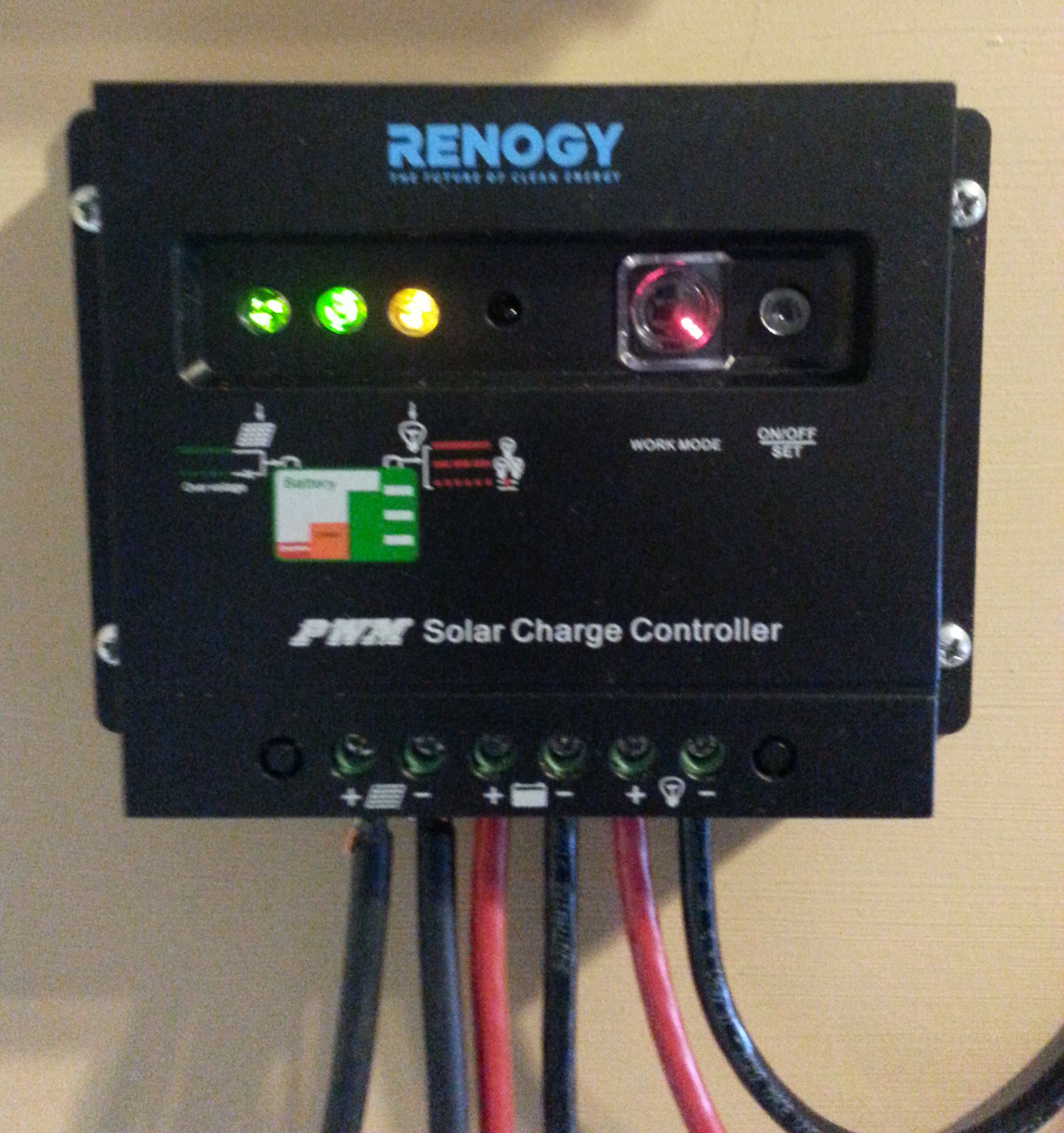
A few hours after this picture was taken, the DC load/inverter light went out (from orange) and the Battery light began winking slowly indicating level full. My system works!